Building an Arcade Fight Stick
When it comes to playing fighting games or certain arcade/MAME games, an Arcade Stick can be nicer than a gamepad. You can really mash the buttons and yank the lever (that’s the technical name for the actual stick).
There are many that you can just buy, and that’s probably the preferred choice. Hori has long been a trusted brand, I actually own a Victrix Pro FS, the Hitbox is getting a lot of buzz because it’s all buttons, no lever, and I’m currently waiting on a Snackbox Micro because of it’s size. Seriously, it’s tiny.
But one thing that most (all?) fight stick have in common is that they have 1 lever (usually emulating a D-Pad) and the face buttons, but no analog sticks. Which is fine for a lot of games, but there are some games that actually would benefit from having one.
One example are Tower Konsumables in MK11, which are triggered by the right analog stick. (Also, navigating the Krypt, but arguably it’s easier to just switch to a gamepad for that).
Arguably, this is a niche case, but building my own fight stick sounded like a fun idea, even knowing that I probably learn a lot of lessons while I’m messing up stuff.
The Finished Build
Just starting with the final controller that I built, warts and all.

The PCB
Now, before we get into buttons, levers, etc., the question is how to actually connect it all to a PC or Console.
If you want something for retro consoles like the SNES or Genesis, then all you really need are some simple components like a shift register, maybe a diode or some resistors.
If you ever built your own mechanical keyboard, your mind might go to a Teensy and just emulate a keyboard – and that would work on a PC, except that you don’t get analog controls. Also, keyboards aren’t supported on most (all?) consoles.
If you want something just for PC use, then a Zero-Delay USB Encoder should be all that you need.
But if you want console support as well, you need something better, that actually properly authenticates and communicates with the console. And if you want it to work on a Playstation 4, you also want something that doesn’t have the 8 Minutes timeout issue – the PS4 tries to authenticate the controller every 8 minutes, and if the board doesn’t handle it, you have to reconnect the controller every time.
Thankfully, there are companies that make all in one boards for consoles, one of which is Brook.
They have a variety of boards, and the one that ticked all my boxes was the PS4+ Audio Fighting Board:
- Supports Switch, XInput, PS3, PS4, and with an extra board, PS5 in PS5 mode
- No 8 Minute PS4 timeout issue
- SOCD Cleaner built-in
- D-Pad and simultaneous Dual Analog stick support
- Some other bells and whistles like Audio support (works on PC as well as PS), a Turbo key, 4 player LEDs
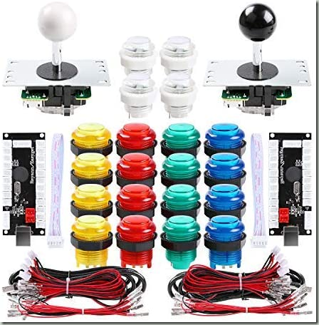
The Lever and Buttons
There is a massive amount of different levers and buttons around, and this is where the customization really comes in. Do you prefer a Japanese Sanwa lever, or another Japanese-style lever? With a Square, Octagonal, or Circular gate? Maybe you prefer a Korean lever? Heck, if you can get your hand on the always-sold-out Golden Lever, that might be a great choice as well. Do you prefer a Ball or Bat Top? Or maybe you don’t want a lever and use Buttons instead, like on a Hitbox or variant.
For your buttons, do you want 30mm or 24mm buttons? Silent or clicky? With a LED in it? In different colors? Convex or Concave?
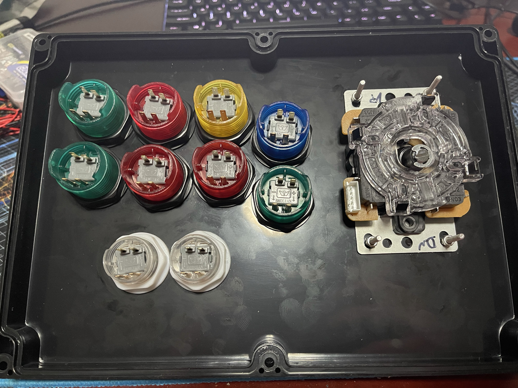
There is no one-size fits all answer, and the hardware can get pretty expensive. I took the easy way out and bought a $40 set on Amazon with a bunch of stuff in it. It’s… not great, the buttons are a bit mushy and sticky, though the levers seem to be authentic Sanwa. It’s a starting point, and the nice thing about buttons is that I can always replace them later with better ones. There’s also a second lever and two zero-delay USB encoders that I don’t need here, but maybe I have use for another project since I have quite a few leftover parts now.
The larger buttons are 30mm, and the smaller buttons are 24mm diameter. The sticks have a 5-pin output cable, which is a common Ground and the 4 directions. Some sticks might have 8-pins, one ground for each of the four directions. The brooks board uses 5-pin, not sure if an 8-pin connection would work by just tying the ground pins together.
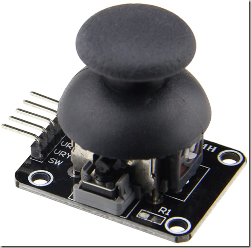
Analog Sticks
When you search for analog sticks, there are many that are meant as replacements/repairs for a PS4/Xbox Controller. These are pretty awful to work with because they have a lot of pins in a weird layout – it’s not a nice even pitch that would just fit on a breadboard/prototyping board. Plus, you need a thunbstick cover, though I’ve seen sets on Amazon that included the thumbstick.

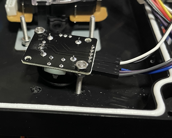
I’m sure they are pretty good as a replacement, but for this project, I went with Analog Sticks that came on a breakout board. These are often advertised as “For Arduino projects” or the like, but they have exactly what I want: A simple 5 pin connection, and a board that just screws in somewhere. The specific ones that I bought don’t seem available on Amazon anymore, but I’ve seen many variations. In the end, they are really just variable resistors anyway, going from 0V to 5V on two different axes, plus a regular button.
The Case
You need to put your stick into some kind of box, and as usual, there’s so many options. Wood? Cheap Crap Plastic box? A cardboard shoebox? 3D Printing your own? Do you want to put a plexiglass cover to allow artwork or glue it on?
I went with a simple option, a plastic project box from Amazon. It needs to be large enough to hold the parts, I picked one that’s 10.4" x 7.2" x 3.7" (263 x 182 x 95 mm).

Stick Layout (and issues with it)
I’ve used arcadesticks before, so I had a rough idea of the layout, which I’ve put together in Affinity Designer to get exact measurements. There are some common layouts, mainly Viewlix and Noir. I went with a Viewlix layout because it seems to be more common for 2D fighters, but it’s taste. I’m not offering the layout for download because it has a lot of issues that I’ll go in, better download a proper template as a starting point.
The nice thing is that if you’re left handed, you can just switch layouts around and put the joystick on the right.
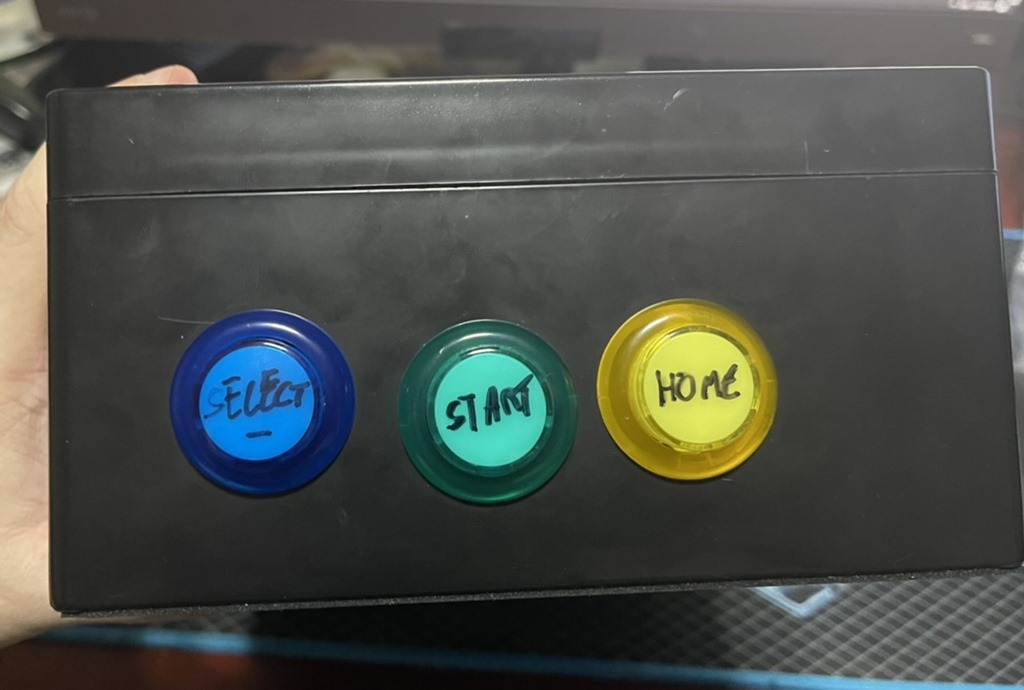
Not shown in this layout are some buttons I mounted on the side. That’s because those aren’t needed during actual gameplay and I don’t want to accidentally press them. I did order some very small push buttons that I didn’t end up using. Select/Start/Home is on one side, and the PS4 Touchpad/Switch Home button is on the other side, along with a turbo button that’s useful for some shooters.

Assembly: Drilling Holes, inserting buttons, getting the spacing wrong
Step one was to print out the template, drill holes using a step bit, and then insert the buttons. For the Joystick, I decided to drill four small holes for an M3 bolt to hold the edges.
Three observations/mistakes here:
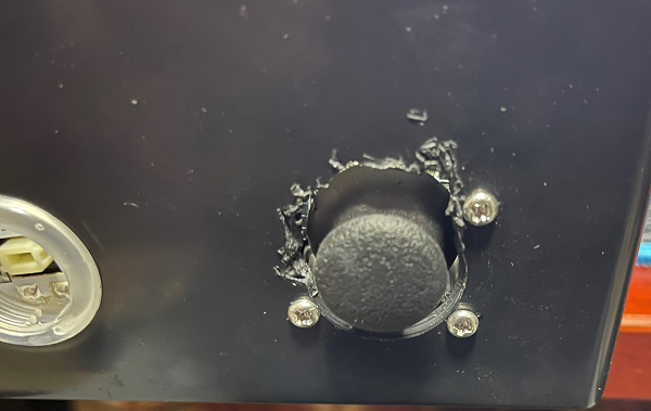
- Step bits are neat, but the plastic shavings get EVERYWHERE. Do it in an area that you can cleanup easily, I expect to find plastic shavings in my room for weeks to come
- Don’t measure the diameter of the button (30mm), but the actual collar/screw that holds it in. I got lucky that I could fasten the buttons, but it is an extremely tight fit – I should’ve added 1mm-2mm extra space around the buttons.
- I didn’t consider that my palms would rest below the buttons. The Select/Start buttons are pretty useless here, because I’d press them accidentally with my palms all the time. it might be possible to salvage, but for this, I just left them unused/disconnected.
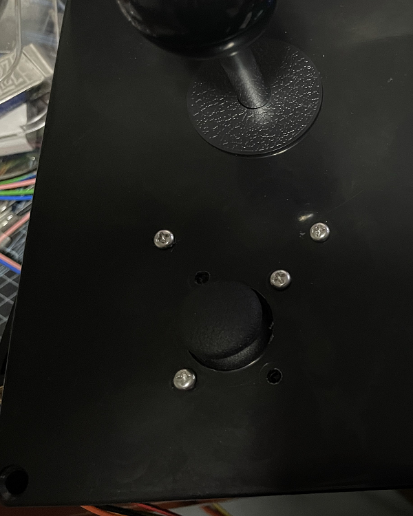
Mounting Analog Sticks
Here’s where I made some more mistakes. I drilled a large hole for the stick, then some smaller holes to mount M3 bolts to hold the board. The problem is that if the stick is too close to the hole, it would scrape the case. I didn’t have long enough bolts to really get an overly stable mount, as the nuts are at the very end of the bolt. (This photo doesn’t show a third nut at the bottom where the bolt is held into the case.
But even if I had them long enough, the problem when moving the analog stick to the corners (top left etc.), I hit the bolt. So it’s not suitable for smooth movements.
Still, it works perfectly well for what I need it for: Tower Konsumables, and 3D camera movements in some games.
I mounted the right analog stick under the main joystick, which is a pretty good position since my hand is well to the left of it. The left analog stick is mounted on the right side of the stick – I don’t really need it all that often. I did mess up the hole spacing on that left stick and had to expand it with some side cutters. Yeah, “Measure twice, cut once” and all that, but oh well – I knew this would be a learning exercise.
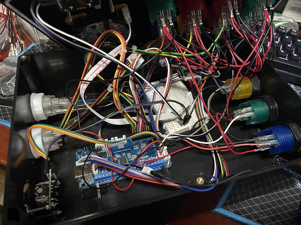
Wires, so many wires
Buttons are in, Lever is in, Analog sticks are in. So, how to wire it all up and end with this beautiful look? Oh boy, this is messy due to bad planning, but as said, I didn’t know what I was doing and figured stuff out as I went.
Now, here’s one criticism of the Brook board: They changed revisions, but didn’t update the docs.
The PDF User Guide shows the old, Rev1 layout:
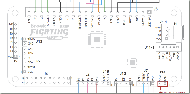
A Rev2 board has those white JST connectors at the bottom. The main product page shows the correct pinouts, but you’ll be going back and forth between the product page and user guide a bit. Not sure if other fighting boards have similar documentation issues.
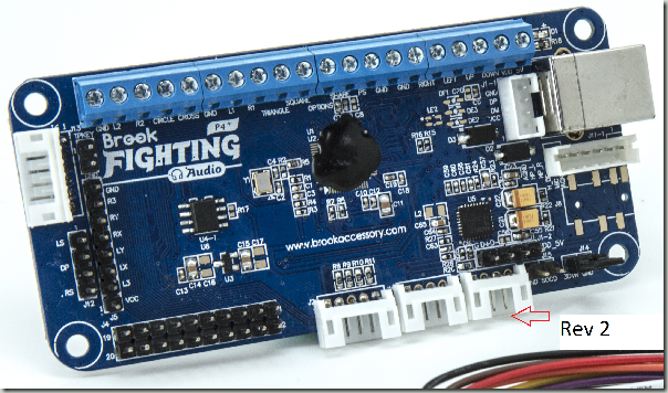
The board has two main connections for the buttons/lever: There is a 20 pin connector (J4), and a set of screw terminals at the top. I bought the Fighting Board cable for an extra $20, which connects to the 20 Pin connector and has a bunch of female spade connectors. I could probably have bought a bunch of spade connectors on wires separately, and in hindsight that would’ve been better because I could use longer cables, but the harness made that part pretty easy.
It’s a bit hard to see which cable connects to which button, here’s the pinout of each of the 4 strands coming from J4:
| Joystick Pinout | |
|---|---|
| Green | Down |
| Yellow | Up |
| Orange | Right |
| Red | Left |
| Black | GND |
| Button Strand 1 | |
|---|---|
| Red | START / OPTIONS |
| White/Red | SELECT / SHARE / BACK |
| Grey | HOME / PS / XBox |
| Button Strand 2 | |
|---|---|
| Red | 2P / Triangle / Y |
| Blue | 1P / Square / X |
| Purple | 4P / L1 / LB |
| Gray | 3P / R1 / RB |
| Button Strand 3 | |
|---|---|
| Orange | 1K / X / A |
| Green | 3K / R2 / RT |
| Yellow | 2K / Circle / B |
| Black | 4K / L2 / LT |
Additionally, there is a wire with a bunch of GND connections for all the buttons.
For the Analog sticks, you need to first remove the jumper on J14, which is the bottom right of the board. Then, you can wire it into J5 on the left. Note that GND and +5V is shared, so you need to split that. You can’t just leave one analog stick floating if you don’t want to use it, as the signals interfere. I don’t know the resistor value to keep it centered if you just want to put something on it that’s not an analog stick. You can’t pull it to Ground or 5V, as those are the extremes of the range. Dead center would be resistance to get it down to 2.5V.
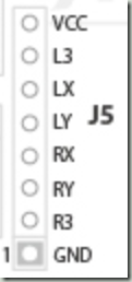
X/Y are the inputs for the analog sticks (there are two axes/two variable resistors per stick), and the L3/R3 is for the button. I used a breadboard and some dupont wire to split the GND/VCC into two, one for each stick. That’s very brittle and gets loose easily, but my soldering iron is still on backorder, after which I’ll definitely come up with a permanent solution.

Different Modes for different systems
This specific board supports different modes to pretend to be a PS3, PS4, Switch, or XInput stick. Do select a mode, hold one of the buttons when plugging in the stick. I believe that XInput is the default, but I usually use it in PS4 mode which gives access to all features even on Windows.
| Modes | |
|---|---|
| 1P / Square / X | Playstation 3 |
| 2P / Triangle / Y | Playstation 4 |
| 3P / R1 / RB | XInput |
| 1K / X / A | Nintendo Switch |
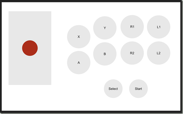
Face Button Naming for Consoles
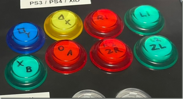
One big annoyance with modern consoles is that they all have different names for their buttons. Between the Xbox, Playstation, and Switch, for example the button labelled X is in three different places. The shoulder buttons are at least named a bit more consistently: R1 on the Playstation, RB on the Xbox, R on the Switch. R2 on the Playstation, RT on the Xbox, ZR on the Switch.
The buttons that I have allow me to remove the top and write on the actual button, which is that I did – top left is Playstation, bottom right is Switch, and the Color coding is for the Xbox, which many Windows games use.
Parts List
The parts list that I used – but see the text on whether I’d recommend them.
| Name | Price | Description |
|---|---|---|
| Brook PS4+ Fighting Board with Audio | $65 | PCB |
| Brook Fighting Board Cable | $23 | Cables to connect PCB to Buttons |
| Qenker 2 Player LED Arcade DIY Parts | $40 | 16 large, 4 small buttons, 2 levers - there are many kits like this on Amazon |
| WMYCONGCONG 10 PCS Game Joystick Breakout Module | $14 | 10 pack analog sticks on a breakout board |
| LeMotech ABS Plastic Electrical Project Case, 10.4" x 7.2" x 3.7" (263 x 182 x 95 mm) | $23 | Box to put it all in |
| Dupont Wire, a Breadboard | $10-ish | Connecting the analog sticks |
| Total | $175-ish | Not counting tools like a drill, step bit, solder iron, pliers etc. |
Conclusion
Was it worth it? Probably not, it’s a lot of money for something that’s ultimately worse than a $150 Hori stick.
Was it fun to do? Heck yeah, it was.
Am I going to try it again, with a proper 3D printed case, clean wiring, and better buttons? Probably!
Is this going to help me win at fighting games? Probably not.